Circuit board prototyping can be found in many different applications and accessories. However, what you may not know is that these little boards have quite the history and dynamic manufacturing process. Here is everything a beginner needs to know about prototype printed circuit boards.
Circuit board history
The circuit boards we know today have been developed from simpler electrical connections from the 1850s, when metal rods were used to connect larger metal, electronic components. Because these large designs were quite bulky and hard to use, engineers created streamlined, simpler versions at the turn of the century. Then in 1925, American Charles Ducas submitted the first patent for creating an electrical current directly on an insulated circuit, giving rise to the name “printed circuit board prototype.”
PCB layout
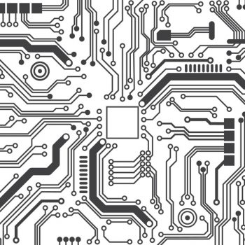
Since circuit board prototyping is so versatile, there is no such thing as a standard board. Each is designed to have a unique function, and their sizes and thicknesses will differ. However, there are details that are universal within the rules of the circuit board world, including spaces between the electrical paths less than 0.4 inches apart. Besides that, everything is unique to the board and its specific purpose.
PCB manufacturing
Simply put, there are two forms of construction processes that engineers use when they assemble their boards, through the hole and surface mount construction.
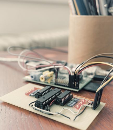
Through the hole- When an engineer mounts electrical components via leads on one side of the board and then solders them onto the copper traces on the opposite side. This is an outdated technology, as this technique is quite time-consuming.
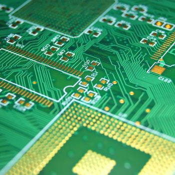
Surface mount construction- With this technique, components have small metal caps that are soldered directly onto their designated side of the board. This method allows for much smaller PCB assemblies that have higher circuit densities.
Raw materials needed for circuit board prototyping
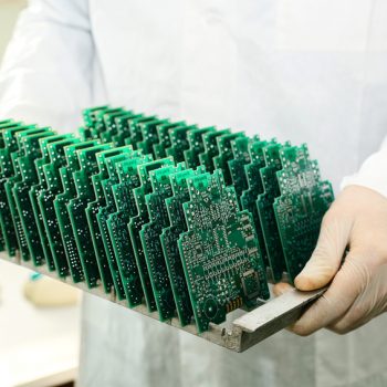
Generally, the most common material is fiberglass that is reinforced with an epoxy resin and copper foil that is bonded to one or both sides. In order to prevent oxidation, once the copper has been etched, it is coated with a layer of tin.
Interested in learning more about circuit boards? Contact our professionals today.


Very well written blog. I really like it and found quite helpful for my knowledge and to my business as well. I am sharing this to my one of my group of electronics also. So promote it you also so that other can also get benefited from this – especially beginners.
You made some good points there. I looked on the net to
learn more about the issue and found most individuals
will go along with your views on this website.
I really love your website.. Pleasant colors & theme.
Did you create this website yourself? Please reply back
as I’m trying to create my very own blog and would like to know
where you got this from or what the theme is named.
Cheers!