Flex Circuits, usually known as Flex PCB, are changing the way that electronics industry is creating new products, initially developed to replace wire harnesses, the Flexible Circuit technology is now breaking the old fabrication paradigms where the size of the PCB was a determining factor in electronics designing.
Through the years PCB Unlimited has built a network of manufacturing partners that include the most Flex PCB savvy factories offshore and in the US. Offering a wide range of high quality solutions, from single sided Flexible Circuits to Rigid-Flex boards, at the best prices.
At today's world Flex Circuits can be found almost anywhere from gadgets as laptops, tablets, cell phones and smartwatches to airplanes and unmanned vehicles. The list of applications for Flexible Circuits keeps growing and growing.
We provide Flex PCB solutions to companies from the following industries:


There is a large list of benefits offered by the Flexible Circuit Technology, it can considerably improve the physical characteristics of a design by reducing both weight and size. The cost and performance advantages of using Flexible Circuits are also points that engineers and designers keep in mind, since this technology is able to offer the following benefits:
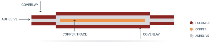
Consisting of a single thin conductive layer, hot-pressed and glued together with a flexible dielectric film to provide electrical insulation and protection from the elements, a single sided Flex PCB is the most basic and most common type of Flex Circuits.
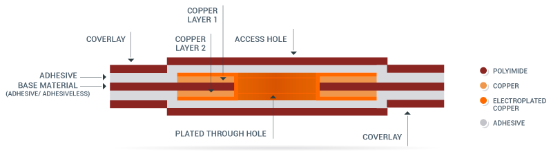
Starting with a Polyimide film as a base layer, two separate conductive layers are then glued and hot-pressed together to both sides of the film. Plated Through Holes (PTH) are used to interconnect the copper layers, and additional layers of polyimide on both sides of the panel brings insulation to the double sided Flex Circuits.
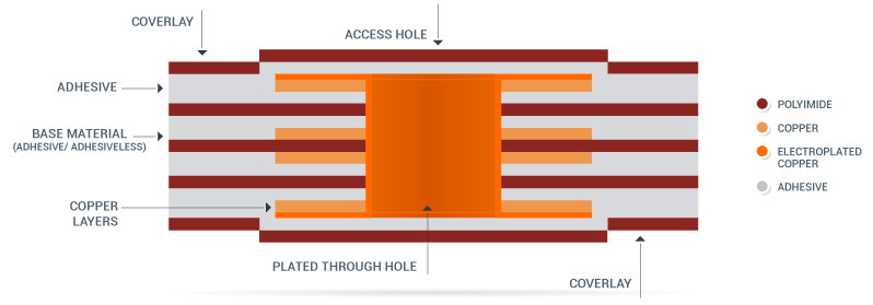
Containing three or more conductive layers, Multilayer Flex circuits manufacturing is performed combining double and single sided Flexible constructions, using adhesive layers to bond them together and interconnecting them by means of plated Vias. Circuit protection and electrical insulation is provided by a Coverlay (usually Polyimide).
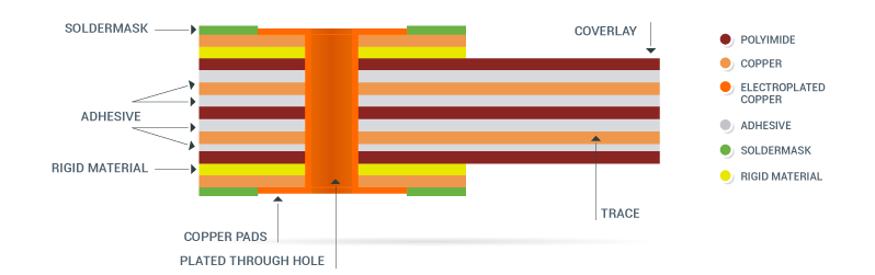
Rigid-Flex Circuits are obtained by laminating together flexible and rigid substrates, providing the design not only with strength but with dynamic adaptability as well. The rigid parts are often used to carry components and the flex substrates serve as interconnection paths.
| Polyimide Films | 0.5 mil (.0005"), 1 mil (.001"), 2 mils (.002"), 3 mils (.003"), 5 mils (.005") |
| Polyester Films | 2 mils (.002") |
| Adhesiveless Base | Polyimide: 0.5 mil (.0005") – 5 mils (.005") Copper: 0.5 oz. (.0007") – 2oz. (.0028") |
| Copper Foils | 0.5 oz. (.0007"), 1 oz. (.0014"), 2 oz. (.0028") |
| Adhesives | Acrylic/Modified Acrylic, Phenolic Butyral, Modified Epoxy |
| Surface Finish | Solder (hot air leveling or electrolytic plating), Electroless Au and Ni |
| Stiffeners | FR-4, polyimide, metal, or customer supplied |
| Other Materials or Finishes | Contact us at: support@pcbunlimited.com |
| Max. Panel Size | 250mm * 450mm |
| Layer Count | 0-6 |
| Minimum Trace Width/Spacing | .003"/.003" (0.5 oz.) .004"/.004" (1 oz.) |
| Minimum Trace to Route Edge Dimension | +/-0.005" |
| Minimum Route Dimensional Tolerance | +/-005" |
| Minimum Tolerance of ZIF Connector to Edge of Flex | +/-003" |
| Minimum Feature to Feature Dimensional Tolerance | +/-0.003" |
| Minimum Corner Route Radius | 0.010" +/-0.0005" |
| Minimum Inside Radius | 0.006" +/-0.0003" |
| Minimum Hole size | +/-0.006" |
| Minimum Slot Width | 0.008" |
| Minimum Annular Ring Size | 0.014" |
| Minimum Space Between Coverlay Openings | 0.010" |
| Minimum Legend Line Width | 0.007" (preferred) |
| Edge of Coverlay Opening to Trace | 0.007" |
| Minimum Inner Diameter or Thermal Reliefs | 0.010" (drill size) |